
미세먼지 PCB 주문 후 수령 및 동작 간단 확인
PCB 및 SMT 주문 제작 후 발송 확인
며칠 전에 미세먼지 측정기 PCB 를 JLCPCB 에 주문 제작 하는 과정을 소개를 해드린 적이 있습니다.
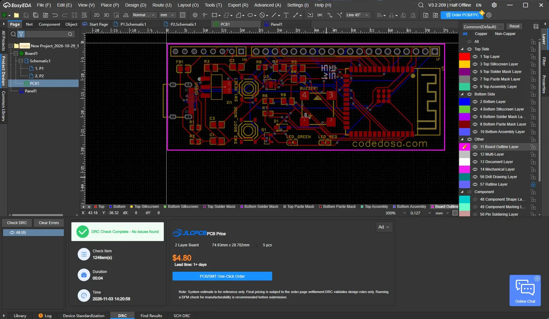
EasyEDA 로 회로를 직접 그리고 거버 파일 까지 직접 생성해서 BOM, CPL 등의 파일을 JLCPCB에 수동으로 주문하였습니다. 11월 4일에 주문을 하고 다음과 같이 JLCPCB 에서 메일이 왔습니다.
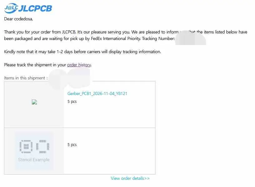
오호라 주문한 PCB와 SMT 작업이 끝나서 배송 코드를 알려줍니다.
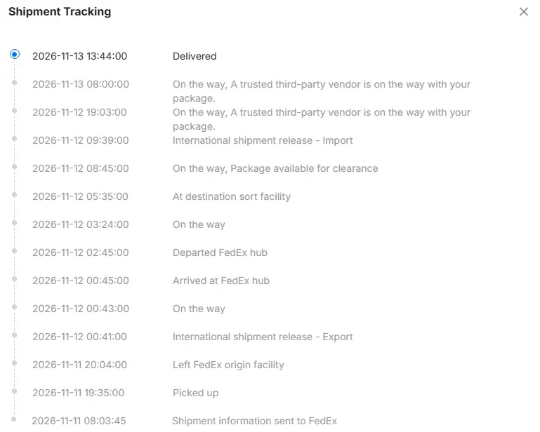
11월 11일에 FedEx 를 통해서 배송이 시작됐다고 나오는 군요. JLCPCB 의 주문 현황 정보에서 이렇게 배송 추적 정보도 확인이 가능합니다. 11일에 배송 출발해서 국내 공항 도착은 하루만이고 택배 회사 통해서 배송까지 이틀 밖에 걸리지 않은거 같습니다. 생각보다 빨리 왔네요.
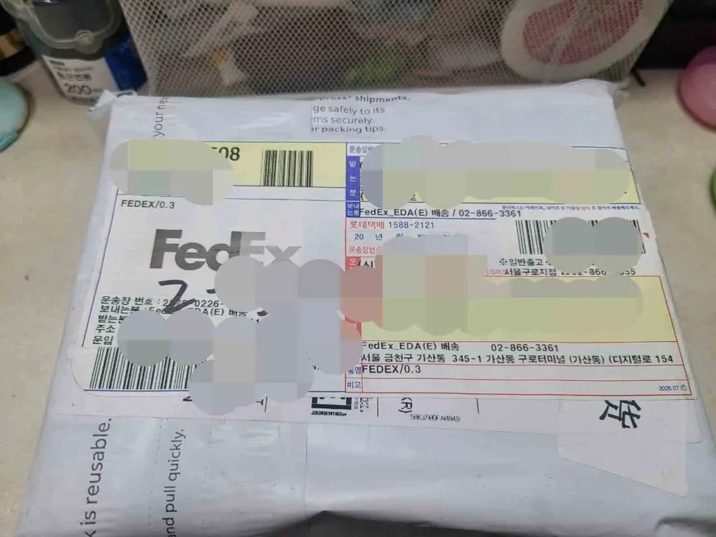
집에서 받은 FedEx 포장 상자입니다. 롯데택배 통해서 배송 받았습니다.
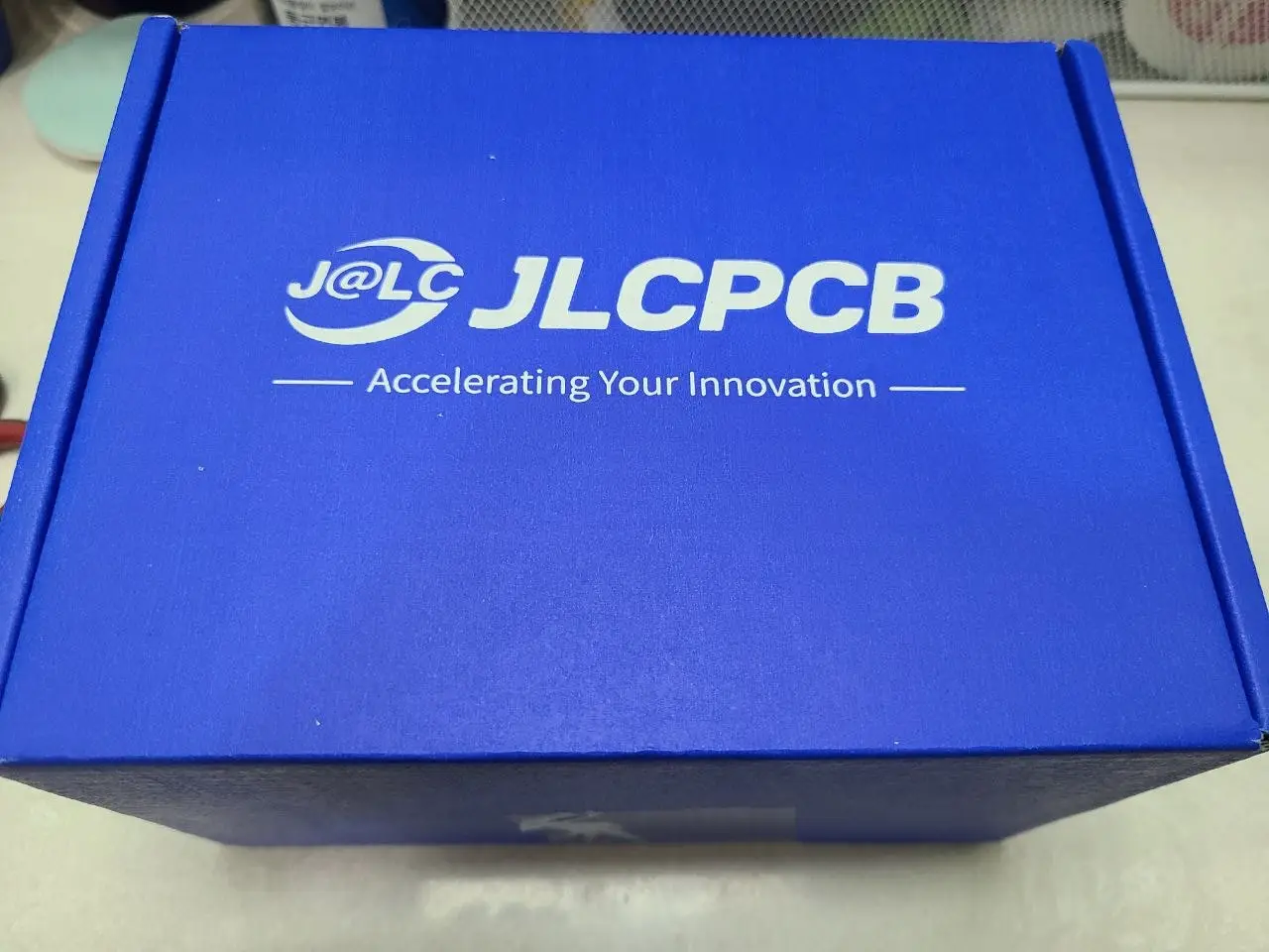
포장 비닐을 뜯으니 파란 색의 박스에 JLCPCB 라고 쓰여 있네요. PCB 가 담긴 상자 치고 깔끔하고 디자인이 괜찮아 보입니다.
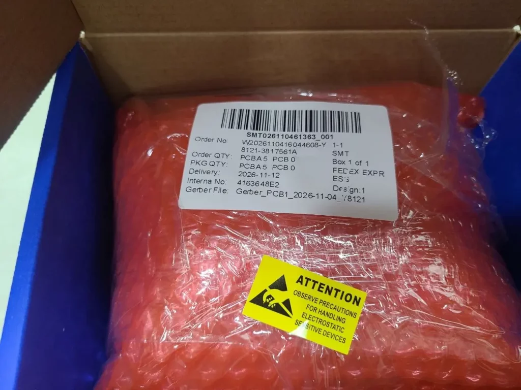
박스 뚜껑을 여니 뽁뽁이로 쌓여져 있는 무언가가 보이는군요. 풀어보니….
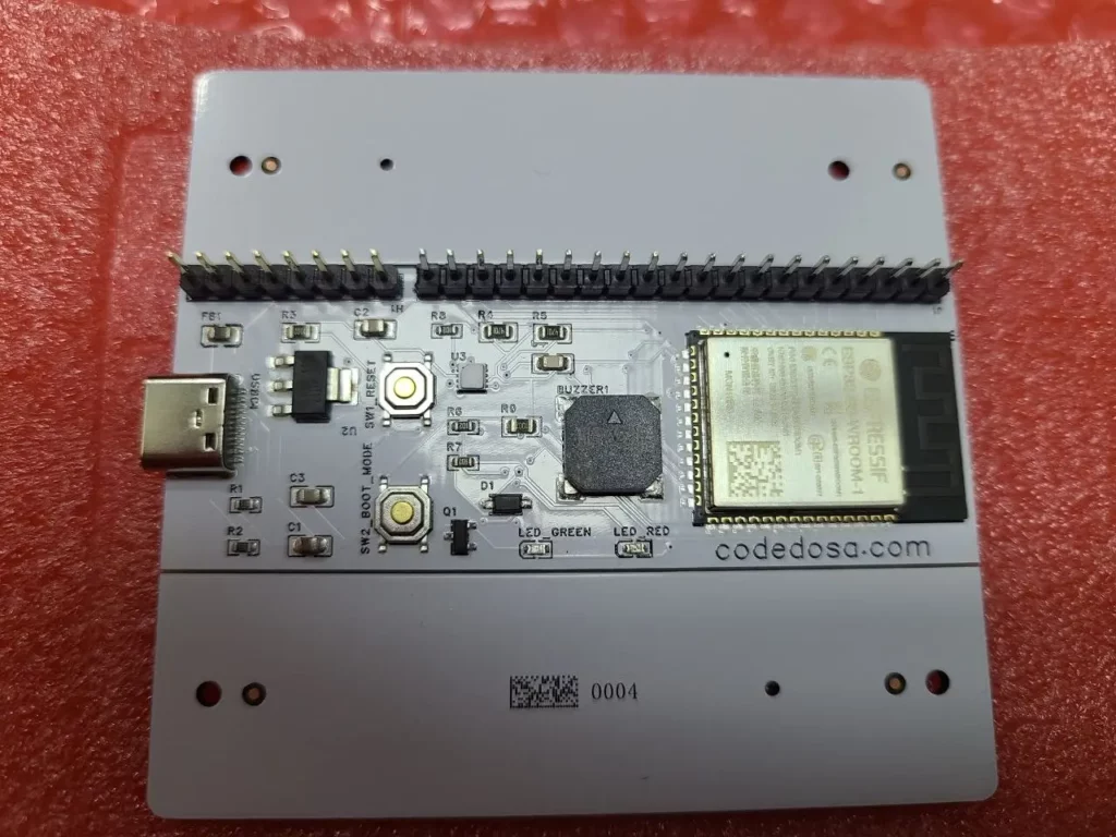
와우! 제가 주문했던 PCB가 드디어 도착했습니다. 저 스스로 만든 PCB가 이렇게 도착하다니 감격스럽군요.
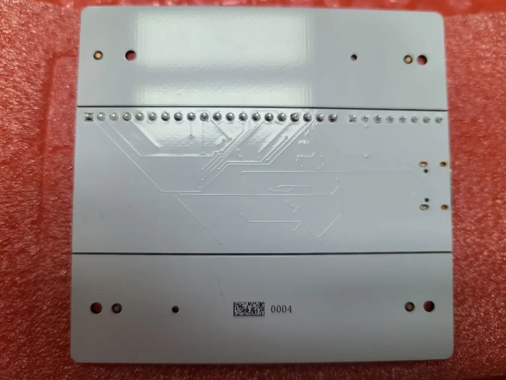
뒤로 돌려보니 납땜이나 부품 부착등이 손색없이 잘 된 상태로 도착했습니다. 이렇게 간단한 PCB도 직접 만들고 SMT 작업까지 저렴한 가격이 할 수 있다니 나름 놀라울 따름입니다.
실제 PCB 동작 확인
자 드디어 제가 직접 제작한 “미세먼지 측정기 PCB” 가 도착했습니다. 2층 짜리 PCB가 잘 도착을 했고 납땜 작업도 손색없이 됐지만 “PCB의 회로가 잘 동작하는건” 별도의 문제입니다.
예전 한창 개발할때 경험으로는 PCB와 SMT 작업이 끝난 보드를 시험할때 꼭 몇군데 잘못된 부분이 있어서 시스템이 제대로 부팅이 안된다던지 의도한 동작이 안된다 던지 하는 부분이 늘 존재했던거 같습니다.
그런 우려가 살짝 됐지만(혹시나 USB 케이블 연결했을때 제대로 동작할까?) 일단 시스템이 정상 동작하는지 확인은 필수 입니다. 그래서 내 PC의 장치관리자를 열고 USB-C 타입 케이블을 미세먼지 측정기 보드에 연결해 봅니다.
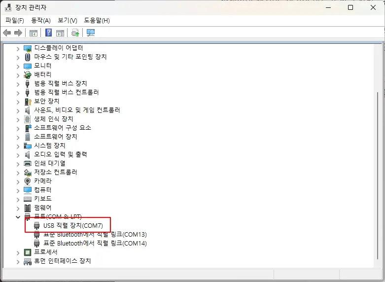
오호라~ USB 케이블을 꽂으니 장치관리자에서 USB 포트가 활성화 됩니다. COM7 으로 나타나는군요.
하지만 과연 ESP32-S3 모듈 포함 시스템이 정상적으로 동작한다는 보장은 없습니다. 그래서 콘솔을 연결해서 실제 모듈이 제대로 인식되는지 확인해 보겠습니다.
esptool.py --port COM7 chip_id
esptool.py --port COM7 flash_id
위 명령어들을 통해 ESP32 모듈 종류와 플래시 사이즈 등을 확인해 보도록 하지요.
PS D:\ESP32\advanced> esptool.py --port COM7 chip_id
esptool.py v4.12.0
Serial port COM7
Connecting...
Detecting chip type... ESP32-S3
Chip is ESP32-S3 (QFN56) (revision v0.2)
Features: WiFi, BLE, Embedded PSRAM 8MB (AP_3v3)
Crystal is 40MHz
USB mode: USB-Serial/JTAG
MAC: 90:70:69:fb:e9:54
Uploading stub...
Running stub...
Stub running...
Warning: ESP32-S3 has no Chip ID. Reading MAC instead.
MAC: 90:70:69:fb:e9:54
Hard resetting via RTS pin...
chip_id 명령으로 읽어보닌 일단 잘 읽어집니다. ESP32-S3 모듈이고 PSRAM 이 8MB 로 나오네요. 일단 인식은 성공입니다.
PS D:\ESP32\advanced> esptool.py --port COM7 flash_id
esptool.py v4.12.0
Serial port COM7
Connecting...
Detecting chip type... ESP32-S3
Chip is ESP32-S3 (QFN56) (revision v0.2)
Features: WiFi, BLE, Embedded PSRAM 8MB (AP_3v3)
Crystal is 40MHz
USB mode: USB-Serial/JTAG
MAC: 90:70:69:fb:e9:54
Uploading stub...
Running stub...
Stub running...
Manufacturer: 46
Device: 4018
Detected flash size: 16MB
Flash type set in eFuse: quad (4 data lines)
Flash voltage set by eFuse to 3.3V
Hard resetting via RTS pin...
이번에는 Flash 사이즈를 확인해 봤습니다. 사이즈가 16 MB 라고 나오는군요. 여기까지 보면 인식이 정상적으로 잘 되고 있습니다. “ESP32-S3-WROOM-1-N16R8” 모듈이 맞는걸 확인했습니다.
여기까지 아주 좋습니다. 그럼 실제로 빌드한 펌웨어 파일이 잘 다운로드 되고 동작하는지 확인해 봐야 겠군요.
예제 소스 빌드 및 펌웨어 파일 다운로드 후 동작
자 그럼 실제 SDK의 예제 소스의 빌드된 펌웨어 파일이 제작한 보드에 정상적으로 다운로드 되고 잘 동작하는지 확인을 해 봐야겠습니다.
일단 예제 소스를 선택해 보겠습니다. SDK 안에는 여러 예제 소스가 있는데 v5.5.6 안에는 다음 경로에 콘솔 테스트용 소스가 들어 있습니다.
D:\$\v5.5.6\esp-idf\examples\system\console\advanced
“advanced” 라는 소스 폴더를 한꺼번에 임의의 경로에 복사를 한 다음, VS Code 로 폴더를 오픈하고 device target 을 esp32s3 로 설정합니다.
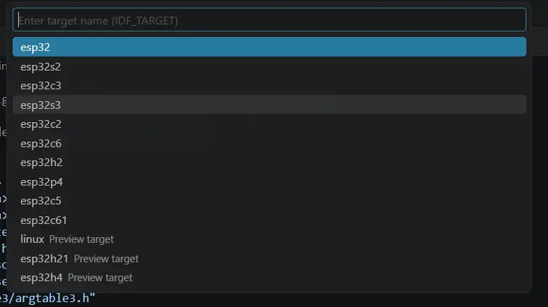
그런 다음 VS code 에서 터미널을 연 다음. idf.py 로 build 를 진행합니다.
Bootloader binary size 0x48d0 bytes. 0x3730 bytes (43%) free.
[848/849] Generating binary image from built executable
esptool.py v4.12.0
Creating esp32s3 image...
Merged 3 ELF sections
Successfully created esp32s3 image.
Generated D:/project/advanced/build/console.bin
[849/849] C:\WINDOWS\system32\cmd.exe /C "cd /D D:\project\advanced\build\esp-idf\es...ced/build/partition_table/partition-table.bin D:/project/advanced/build/console.bin"
console.bin binary size 0xd5b10 bytes. Smallest app partition is 0x100000 bytes. 0x2a4f0 bytes (17%) free.

Project build complete. To flash, run:
 idf.py flash
or
 idf.py -p PORT flash
or
 python -m esptool --chip esp32s3 -b 460800 --before default_reset --after hard_reset write_flash --flash_mode dio --flash_size 4MB --flash_freq 80m 0x0 build\bootloader\bootloader.bin 0x8000 build\partition_table\partition-table.bin 0x10000 build\console.bin
or from the "D:\project\advanced\build" directory
 python -m esptool --chip esp32s3 -b 460800 --before default_reset --after hard_reset write_flash "@flash_args"
(venv) PS D:\project\advanced>
그랬더니 위와 같이 펌웨어 빌드가 완료가 되었습니다. 그럼 idf.py -p COM7 flash 명령어로 펌웨어를 다운로드 해 보겠습니다.
Writing at 0x000c2025... (85 %)
Writing at 0x000c7b7b... (88 %)
Writing at 0x000cf1c1... (91 %)
Writing at 0x000d53b2... (94 %)
Writing at 0x000db62f... (97 %)
Writing at 0x000e0e58... (100 %)
Wrote 875280 bytes (553701 compressed) at 0x00010000 in 4.8 seconds (effective 1473.4 kbit/s)...
Hash of data verified.
Compressed 3072 bytes to 117...
Writing at 0x00008000... (100 %)
Wrote 3072 bytes (117 compressed) at 0x00008000 in 0.0 seconds (effective 828.0 kbit/s)...
Hash of data verified.

Leaving...
Hard resetting via RTS pin...
Done
오호라 확실히 esp32s3 가 다운로드 속도도 빠르네요. 그럼 “idf.py -p (포트) monitor” 명령어로 콘솔로 부팅이 잘 되는지 확인해 보겠습니다.
entry 0x403c88a4
--- 0x403c88a4: call_start_cpu0 at D:/esp/v5.5.6/esp-idf/components/bootloader/subproject/main/bootloader_start.c:27
I (198) cpu_start: Multicore app
I (206) cpu_start: GPIO 44 and 43 are used as console UART I/O pins
I (207) cpu_start: Pro cpu start user code
I (207) cpu_start: cpu freq: 160000000 Hz
I (208) app_init: Application information:
I (212) app_init: Project name:     console
I (216) app_init: App version:      1
I (220) app_init: Compile time:     Nov 17 2026 21:51:14
I (225) app_init: ELF file SHA256:  fd529551c...
I (229) app_init: ESP-IDF:          v5.5.6
I (233) efuse_init: Min chip rev:     v0.0
I (237) efuse_init: Max chip rev:     v0.99
I (241) efuse_init: Chip rev:         v0.2
I (244) heap_init: Initializing. RAM available for dynamic allocation:
I (251) heap_init: At 3FCA5810 len 00043F00 (271 KiB): RAM
I (256) heap_init: At 3FCE9710 len 00005724 (21 KiB): RAM
I (261) heap_init: At 3FCF0000 len 00008000 (32 KiB): DRAM
I (266) heap_init: At 600FE06C len 00001F7C (7 KiB): RTCRAM
I (273) spi_flash: detected chip: generic
I (275) spi_flash: flash io: dio
W (278) spi_flash: Detected size(16384k) larger than the size in the binary image header(4096k). Using the size in the binary image header.
I (291) sleep_gpio: Configure to isolate all GPIO pins in sleep state
I (297) sleep_gpio: Enable automatic switching of GPIO sleep configuration
--- WARNING: Writing to serial is timing out. Please make sure that your application supports an interactive console and that you have picked the correct console for serial communication.
--- WARNING: Writing to serial is timing out. Please make sure that your application supports an interactive console and that you have picked the correct console for serial communication.
--- WARNING: Writing to serial is timing out. Please make sure that your application supports an interactive console and that you have picked the correct console for serial communication.
음 이상합니다. 콘솔 프롬프트가 나타나지도 않고 엔터를 입력할 때마다 WARNING 메시지가 뜨는 군요. 뭔가 이상해서 원인을 찾아보니… 지금 현재 사용하는 UART 라인 설정이 잘못 됐네요.
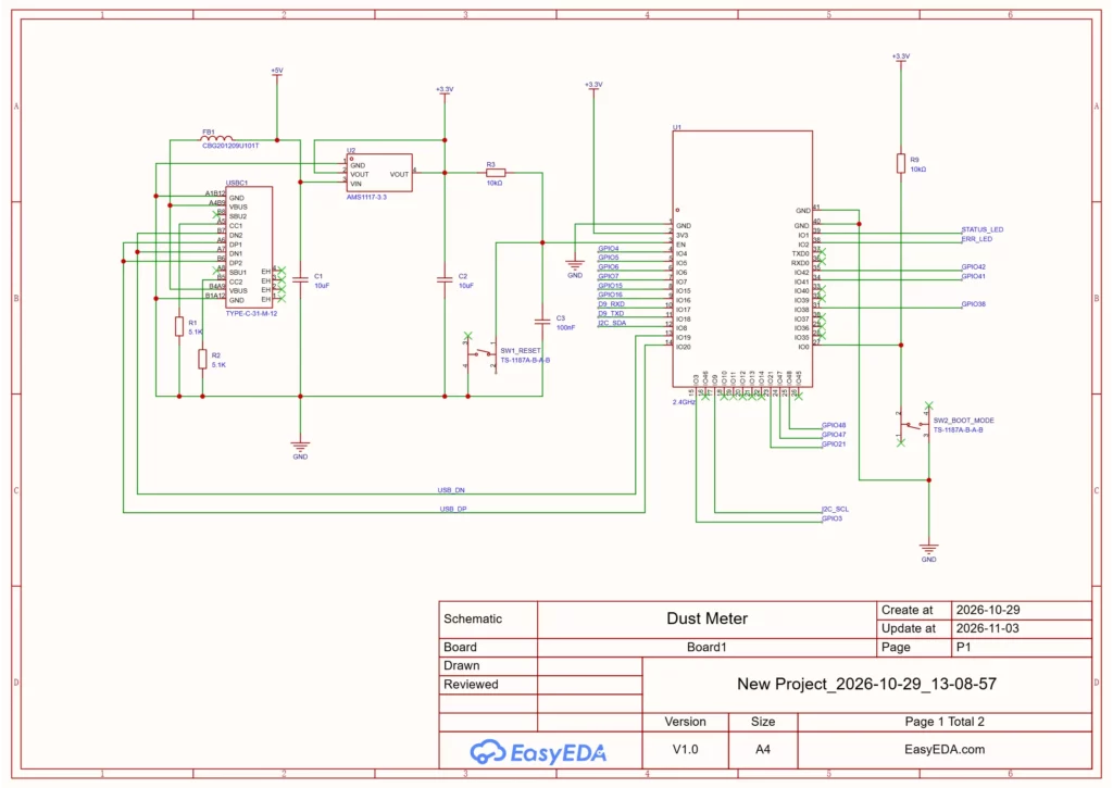
지금 미세먼지 측정기 보드의 회로도에는 IO19/20 번을 USB-C 커넥터로 연결해 놓은 상태인데, 이게 SDK 상에서 설정이 잘못됐나 봅니다.
이때 “idf.py menuconfig” 로 들어가 보겠습니다.
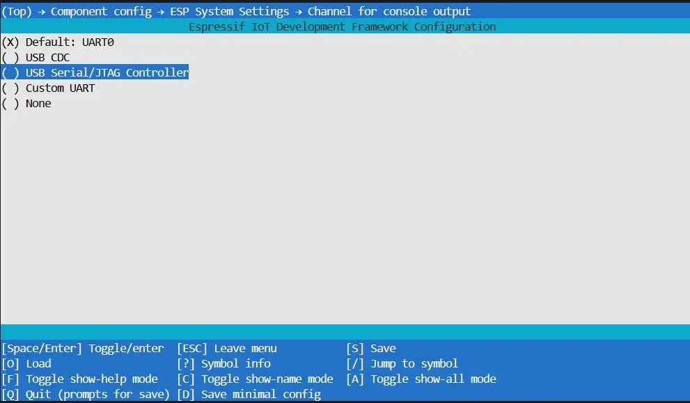
component config – ESP System Settings – Channel for console output 이 UART0 로 설정이 되어 있더군요. 지금 회로 상으로는 USB Serial/JTAG Controller 로 설정해야 Rx/Tx 데이터가 정상적으로 전송됩니다.
또한 Flash 사이즈는 16 MB도 설정을 변경해 주세요.
이렇게 설정 후 저장 후 다시 빌드 후 다운로드 해봤습니다.
entry 0x403c88a0
--- 0x403c88a0: call_start_cpu0 at D:/esp/v5.5.6/esp-idf/components/bootloader/subproject/main/bootloader_start.c:27
I (194) cpu_start: Multicore app
I (203) cpu_start: Pro cpu start user code
I (203) cpu_start: cpu freq: 160000000 Hz
I (204) app_init: Application information:
I (204) app_init: Project name:     console
I (204) app_init: App version:      1
I (204) app_init: Compile time:     Nov 17 2026 22:17:55
I (204) app_init: ELF file SHA256:  376ae172e...
I (204) app_init: ESP-IDF:          v5.5.6
I (204) efuse_init: Min chip rev:     v0.0
I (205) efuse_init: Max chip rev:     v0.99
I (205) efuse_init: Chip rev:         v0.2
I (205) heap_init: Initializing. RAM available for dynamic allocation:
I (205) heap_init: At 3FCA55E8 len 00044128 (272 KiB): RAM
I (206) heap_init: At 3FCE9710 len 00005724 (21 KiB): RAM
I (206) heap_init: At 3FCF0000 len 00008000 (32 KiB): DRAM
I (206) heap_init: At 600FE06C len 00001F7C (7 KiB): RTCRAM
I (207) spi_flash: detected chip: generic
I (207) spi_flash: flash io: dio
I (208) sleep_gpio: Configure to isolate all GPIO pins in sleep state
I (208) sleep_gpio: Enable automatic switching of GPIO sleep configuration
I (209) main_task: Started on CPU0
I (209) main_task: Calling app_main()
I (219) example: Command history enabled

This is an example of ESP-IDF console component.
Type 'help' to get the list of commands.
Use UP/DOWN arrows to navigate through command history.
Press TAB when typing command name to auto-complete.
Ctrl+C will terminate the console environment.
esp32s3>
오호. 뭔가 프롬프트가 나타났습니다. 엔터를 치고 version 을 입력하니
esp32s3> version
IDF Version:v5.5.6
Chip info:
        model:ESP32-S3
        cores:2
        feature:/802.11bgn/BLE/External-Flash:16 MB
        revision number:2
esp32s3>
콘솔 동작이 잘 하는 군요. 일단 여기까지 해서 USB포트를 통해 시리얼 콘솔 사용하는 것까지 정상적으로 구동 되는 걸 확인하였습니다.
미세먼지 측정기 PCB가 일단 부팅도 잘되고 콘솔 까지 잘 동작하는 게 확인되었군요. 아직은 이르지만 나름 뿌듯해 집니다. 이제 다음 글에서는 미세먼지 PCB의 전체적인 정상동작 확인과 실제 미세먼지 측정기를 구현하는 것에 대해 기술해 보도록 하지요.